

Let's build the simplest ALU ever
The ALU is an electric circuit that performs arithmetic operations. Learn how it works by building one.

In a nutshell
ALU stands for Arithmetic Logic Unit. Simply put, the ALU is an electric circuit that performs arithmetic operations.
The ALU is one of the building blocks of the CPU. It's the mathematical brain responsible for arithmetic operations like addition or subtraction and logic operations like conjunction—AND— or disjunction—OR—.
Let's create a small ALU that can perform two operations: addition and conjunction, to better understand all this.
If you don't know what Logic Gates are, I'd recommend reading this article about them.
Simplest ALU ever: 1-bit ALU
This "simplest ALU ever" will perform only two operations in one single bit:
Adding two binary numbers together.
Perform the conjunction operation—AND—.
Therefore, we need two inputs as operands and one input to choose whether to calculate the AND or the addition.

This circuit will perform "Input A + Input B" or "Input A AND Input B." One operation or the other, but not both at the same time. The Output Result will return the result of the operation.
In this example, we are dealing with electrical currents. An input means electrical current flowing in, while an output means electrical current flowing out. So when there is some positive voltage, we refer to it as a 1 or True; when no current flows, that is 0 or False.
A few examples of operations that this ALU can perform are:
1 + 0. The Output Result should be 1.
True & False. The Output Result should be False.
Before we build anything, we need to explain the three components that will form our ALU. Then we will combine them to create the circuit of this ALU.
Component 1: Half Adder
A Half Adder adds two binary numbers together.
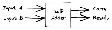
In a nutshell, the Half Adder calculates "Input A + Input B." Since the values can be either zero or one, then the operations are "0+0", "1+0", "0+1" and, "1+1".
For example, when the current is flowing in Input A (one), and no current is flowing in Input B (zero), the circuit will return a positive current in the Result Output (one).

The table for the Half Adder is:
Input A Input B Output Overflow Output Result 0 0 0 0 0 1 0 1 1 0 0 1 1 1 1 0
The Result output is the sum of the inputs in one bit. Yet, one bit is not always enough; for example, the result of "1 + 1" requires two bits.
Let's review the Overflow in one example.

If you are not used to binary, adding "1+1" is a weird operation. The result is 2dec in decimal base or 10bin in binary. Therefore, we need two bits: "1" and "0"; yet, the Result Output is only one bit. Therefore, the first digit from the left of 10bin: "1" is considered an overflow.
If you want to know more about how to build the Half Adder, check out my article on Addition.
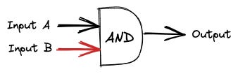
Component 2: AND
For the AND operation, we consider no current to be False. Whereas when there is current, we consider it True.
There is a Logic Gate that performs this operation, the AND logic gate.

The circuit returns the operation of "Input A AND Input B." That means that current will flow through the Output only when current flows through both inputs.
Input A Input B Output False (0) False (0) False(0) False (0) True (1) False (0) True (1) False (0) False (0) True (1) True (1) True (1)
Take a look at the example of current flowing only through Input B (False AND True = False). No current flows through the Output, which is the same as saying it's False.
Only when current flows through both inputs, the Output also returns current.

The previous example is the operation "True AND True = True."
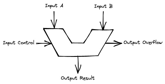
Component 3: Multiplexer or Mux
We need a component that selects the addition or the AND operation. This component is the Multiplexer (also written as Mux). The Multiplexer receives two inputs and returns the value of one of them based on the Input Control.

When the Input Control is 0, the Output is whatever Input A is. When the Input Control is 1, then the Output is the Input B. This table summarizes it.
Input A Input B Input Control Output A (1 or 0) B (1 or 0) 0 A A (1 or 0) B (1 or 0) 1 B
For example, when Input Control is zero and Input A is one, the Output will be one.

The table for this example would be:
Input A Input B Input Control Output 1 0 0 1
Simplest ALU Ever: Circuit
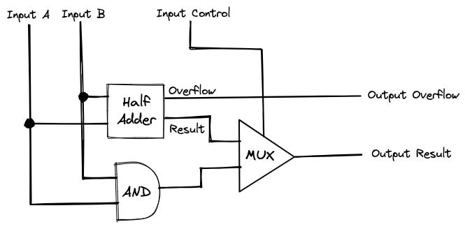
Let's review again what we want to build: a circuit that can perform different operations. Specifically, "Input A + Input B" and "Input A AND Input B."
The operands of the operations are Input A and Input B, while the Input Control selects the operation to perform. On the other hand, the Output Result will return the result of the operation.
The Output Overflow returns extra information about the result. In this case, it returns whether the addition had an overflow or not.
Summary table of the ALU.
Input A Input B Input Control Output Result Output Overflow A B 0 A + B Half Adder Overflow A B 1 A & B (ignored)
Let's take a look at one example: 1 + 0.

To perform addition, we want Input Control as "0" or without electrical current. For the operands: "1" and "0", we send some current through Input A to represent "1" and leave Input B without current for "0".
The result is the calculation of "1 + 0", which is 1. Therefore, the Output returns electrical current representing "1".
The table of this example would be:
Input A Input B Input Control Output Result Output Overflow 1 1 0 1 0
Circuit
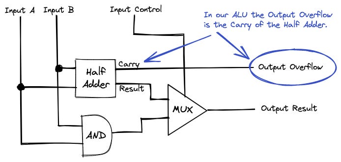
Let's go into the details of how the ALU performs the operations listed. The following is the circuit combining the components explained earlier.

Let's take a look at the previous example or 1 + 0 with this circuit.
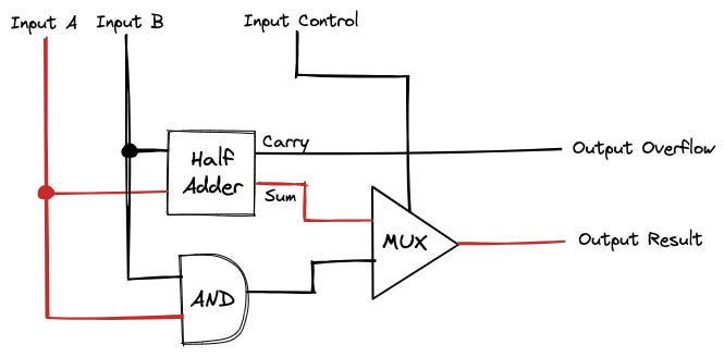
The Input A flows to both the Half Adder and the AND components. The AND component returns no current (True AND False = False) while the Half Adder returns current in the Result Output because (1 + 0 = 1).
Note: 1 is considered True, and 0 is considered False in the boolean operation AND.
The Outputs of the AND and the Half Adder flow into the MUX (Multiplexer). There, the Mux selects one of both inputs depending on the Input Control. In our example, the Input Control has no current, which means that the Mux selects the Half Adder.
The list of arithmetic and logical operations of our ALU is very limited: addition and conjunction. Moreover, it works only with one bit of data. Yet, this simple ALU has two main features of any ALU: Input Control and Flags.
Input Control

The Input Control selects which operation to perform. This ALU can only choose two operations, which means that one Input Control is enough. Yet, most ALUs have many of these Input Controls to be able to choose the desired operation.
Flags
Our ALU also has one flag, the Output Overflow. A flag is an output that gives information about the result of the operation. For example, the result of the addition did not fit in the Output Result of one bit.
Other common flags are whether the result is zero or negative.
"Most famous ALU" versus "simplest ALU ever"
The most famous ALU was developed in the early 1970s and could handle more than 50 operations on four bits. This ALU had more than 70 Logic Gates and was the first one to fit inside a chip.
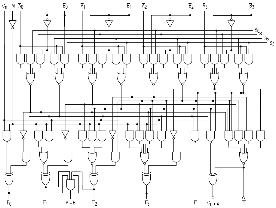
Compare this circuit to ours:
I'd say we did a good job simplifying the ALU. Although we might run into some limitations if we try to build a computer with it 😅
ALU versus FPU
Even though current ALUs are much more complex, they still share a common feature with those explained in this article. They work only with integer binary numbers (for example, 1001 + 1100). ALUs do not handle 2.5 or 3.14. The representation of these numbers is left to the software with the Fixed or Floating Point Representation.
Yet, Floating Point representation has become so universal and important that engineers created a chip for it, the Floating Point Unit or FPU. This chip is similar to the ALU in functionality, but it performs operations with Floating Point numbers, not binary integers.
FPUs are part of modern CPUs, and the CPU is responsible for selecting the operation either in the ALU or the FPU.